
500MW Tangential Oil/Gas Fired Furnace
PlantSim Unit 1 has a C-E Tilting Tangential Firing System. Fuel and air are introduced to the furnace through four windbox assemblies. The fuel and air streams are designed to create a rotating firing action in the center of the furnace.
The maximum continuous rating (MCR) is 3,560,000 lb/hr of main steam flow at 2500 psig and 1005 F at the superheater outlet with a reheat flow of 3,172,000 lb/hr at 551 psig and 1005 F with a normal feedwater temperature of 473 F.
There are four Boiler Circ. Water Pumps, two Forced Draft Fans, and one Gas Recirc Fan.
Fossil Boiler Furnace Specifications
Boiler Furnace Type
Power Rating: 510 MWe
C-E Tangential Oil/Gas Fired Furnace
Steaming Rate
Steam delivered: 3,558,700 lbm/Hour
Steam Conditions
Steam temperature at superheater outlet: 1005 F
Steam pressure at superheater outlet: 2500 psig
Steam temperature at reheater outlet: 1000 F
Steam pressure at reheater outlet: 524 PSIG
Efficiency
89.86%
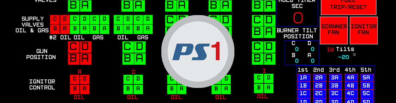
Burners
4 windbox assemblies located in the furnace corners with adjustable tilting nozzle tips. Each windbox includes five fuel compartments with a retractable oil gun. Compartments between each fuel compartment are used for admission of secondary air.
Fuel Fired
256,400 lb/hr
Gas Temp. Entering Air Heater
630 F
Gas Temp. Leaving Air Heater
291 F
Air Temp. Entering Air Heater
110 F
Air Temp. Leaving Air Heater
498 F
Forced Draft Fans
Two fans with inlet damper control
Recirculation Fans
One fan with variable inlet vane control
Air and Flue Gas System
Two FD Fans and One Gas Recirculation Fan
A detailed simulation of the air and flue gas recirculation system is simulated. This includes two forced draft fans, one gas recirculation fan, two Ljungstrom regenerative air pre-heaters and all damper and ducts associated with this equipment. The model responds accurately to the variations in temperature, flowrate and pressure of primary air, secondary air and flue gas.
Fuel System
Oil/Gas Fuel
A detailed simulation of the air and flue gas system is simulated, including two forced draft fans, one gas recirculation fan, two pre-heaters, and all damper and ducts associated with this equipment. The model responds accurately to the variations in temperature, flowrate and pressure of primary air, secondary air and flue gas.
Four windbox assemblies are located in the furnace with adjustable tilting nozzle tips. The nozzel tips can be tilted up or down through a total angle of 60 degrees. Each windox includes five fuel compartments with a retractable oil gun. Compartments between each fuel compartment are used for admission of secondary air.
Water-Steam Circuit
The water fluid circuit includes the condenser discharge that is pumped up to the drum through a series of pumps and feedwater heaters. The path consists of:
- Two condensate pumps
- Low-pressure feedwater heaters
- 2 Boiler feed pumps
- High-pressure feedwater heaters
- Economizer
The boiler circulating pumps take water from the steam drum into the front and rear waterwall inlet drums. From the waterwall inlet drums the water feeds the furnace wall tubes. The water rising in the furnace tubes absorbs heat and is then discharged into the steam drum. The boiler water mixes in the steam drum with the water supplied from the economizer and flows through the downcomers into the boiler circulating pump. Saturated dry steam leaves the steam drum and passes through superheaters and then through to the high-pressure turbine. Steam is then passed to the re-heaters at reduced pressure and then through the IP turbine and then on to two low-pressure turbine stages.
Electrical System
The electrical system model includes the major loads on the 4160V busses; specifically, the motors for circulating water pumps, FD fans, Fuel Oil Burner pumps, condensate pumps, and gas recirculation fan.
Some 480V bus equipment is also modeled such as: L.P. heater drain pumps, Cooling water pumps, Condenser vaccum pumps, and Aux oil pumps. Remaining 480V Hard Panel loads are modeled with loads representing the electrical characteristics of the equipment.
A breaker accomplishes generator synchronizing. All modes of synchronizing, i.e., manual, digital synchronizer and load control, and computer, are included. The excitation system model includes manual and automatic control of field current. Reverse power trip logic is also modeled. The electrical system is interfaced with the emulated operator interfaces for the DCS HMI and hard panel.
During electrical system simulation, expected changes in voltage, current, active and reactive power throughout the system can be seen when breakers are closed or opened, motor loads are changed, generator is synchronized, and excitation and turbine power are controlled. Generator load angle (i.e., the phase angle of the generator induced emf relative to the generator terminal voltage- not available in plant instrumentation) is also calculated by the model. This can be monitored to understand the generator dynamics as the load and excitation are changed.
Control System
The control system is a simulation of the Bailey Infi90 control logic with approximately one hundred nintey emulated operator displays and hard panels. Systems controlled include:
- Unit Control
- Turbine Control
- Boiler Control
- Fuel Control
- Air Flow Control
- Feedwater Control
- Steam Temperature Control
- Auxiliary Steam Control
- Electrical System Control